Audio circuits
Viewed products
-

Phono preamplifier circuit
We present you a retro assembly. This...


Phono preamplifier circuit
We present you a retro assembly. This circuit was absolutely necessary years ago for us to listen to our vinyl discs. We all know what a preamplifier is, but what about R.I.A.A? R.I.A.A is a “Recording Industry Association of America”.
Data sheet
| Design | Schema and circuit |
| View | No display |
| Supply voltage | 24 Volts |
| Electronic | Analog electronics |
| Photo | Yes |
More info
This association proposed certain corrections to be made at the time of recording and reproducing vinyl discs so that their sound quality could be better.
This correction soon became a standard. Therefore, all turntables had to be made according to this correction.
We suddenly had this idea since we wanted to listen to our vinyl discs from last year. The problem is that our amplifier doesn’t have a turntable input, which means that it doesn’t have the R.I.A.A correction either. So, we rolled up our sleeves and this is the result.
Now we can connect the exit of our circuit to the amplifier’s auxiliary entrance. The circuit is integrated in the interior part of the turntable, and we have used its power source to empower our circuit, which consumes merely 20mA. An electronic scheme is quite simple; it consists of an integrated circuit and some other components.
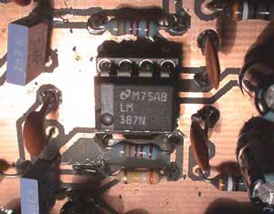
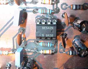
The integrated circuit can be a NE542 or a LM387, each of them will do, they are double operational low volume amplifiers. The only requirement is that they are empowered with 15 volts.
The resistors and the condenser R2, R3, C5, C6 form the filter of the R.I.A.A correction. This filter is nothing more than a curve on the following graphic.
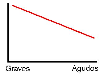
That is to say, our filter (the R.I.A.A) correction actually amplifies deep frequencies and tones down the high-pitched ones.
The wiring diagram.
The circuit board.
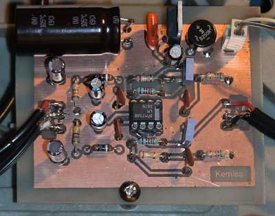
A photo of the assembly of our previous stereo R.I.A.A. Since we didn’t have enough space, we had to tumble the 1.500 uF electrolytic condenser so that it doesn’t hit the lid of our turntable.
As you can see in the photo, we made a ground plane on our printed circuit board, that is, we covered the negative pole with a large quantity of copper on both sides. Doing this, you can manage a better shield against the buzzing. If you don’t know how to make a ground plane, consult our tutorial about how to create a ground plane with Eagle.
In this assembly, when we are at the printed circuit board vision, just by pressing the icon  a ground plane will be created.
Let’s check the compatibitility of the two circuits that are integrated in the assembly. Both LM387 and NE542 can be used without problems, with a 15 volt power.