Power supply circuits
Viewed products
-

Full wave precision rectifier
This precise full-wave-rectifier is a...


Full wave precision rectifier
This precise full-wave-rectifier is a circuit made to rectify those values that a normal bridge rectifier cannot rectify.
The diminution of the diode bridge rectifier’s typical power is (obviously, it depends on the type of the diodes) of the 0,7 volts-an approximate value.
Data sheet
| Design | Schema and circuit |
| View | No display |
| Supply voltage | 12 Volts |
| Electronic | Analog electronics |
| Photo | Yes |
More info
Bridge rectifier with diodes.

What happens if we want to rectify 0.5 volts of the alternating current and convert it into 0.5 volts of the direct current?
Applying the above circuit, the diode bridge rectifier, we won’t obtain an exit (0 volts) between the + and – extremes of the diodes, since the diminution of the power in diodes will prevent the signal from being rectified.
The solution lies in constructing the circuit which will be able to rectify the alternating current practically from 0 volts.
This circuit is our precise full-wave rectifier. It is capable of rectifying the milivolts’ power in the alternating current and converting it to direct current, using the electrolytic condensers’ filters. The circuit is quite simple. We have integrated the source of power so that the assembly can be more compact.
The mentioned source of power is to be symmetric and of +-12 volts so that the integrated circuit TL072 can work properly and the rectification can be effective. The application of this circuit like a full-wave rectifier is perfectly adapted to the necessities of the current clamp for our household.
To create this circuit, we have to rectify the power given by our transformer, which ranges from milivolts to more than 2 volts in the alternating current..
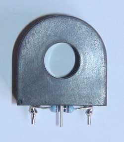
The transformer used in the current clamp.
The electric scheme of the precise full-wave rectified circuit.
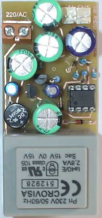
The circuit board.
At the pin 7 of TL072 integrated circuit we have the wave rectification of the alternating current and the components C1, C2, C3, R5, R6 form part of the rectification filter so that the output can be a direct current. The diodes 1N4148 rectify the positive half wave.
If we wish to rectify the negative half wave, we have to invert the direction of the diodes.
A photo of the finished circuit.