Audio circuits
Viewed products
-

Vu meter stereo
This simple circuit is based on the...
 View larger

Vu meter stereo
This simple circuit is based on the well-known integrated circuit LM3915.
Data sheet
| Design | Schema and circuit |
| View | Led |
| Supply voltage | 12 Volts |
| Electronic | Analog electronics |
| Photo | Yes |
More info
The main characteristic of this integrated circuit is its power to manage 10 LED-s (Light Emitting Diodes) in logarithmic scale with a difference between the 3dB LED-s, which it can turn on the “slash” or on the “dot”. The other integrated circuit, the CA3130 is in charge of amplifying and rectifying the audio signal to the entrance of LM3915.
We have included a power regulator in the circuit, a 7812, and that is why the power should be between 13,5 and 20 volts.
To adjust the vu-meter to 0dB, we can download any free programme for Windows which will generate BF, http://www.marchandelec.com/fg.html, for example, which doesn’t even need to be installed.
With the exit adjusted to 1000 Hz and 0dB in the “sine” mode, we shall move the trimmer R1 until the seventh led of our assembly is lit on, and it will correspond with 0dB. If we wish the LED-s to turn on the “slash”, we’ll have to short-circuit the jumper of the circuit marked as B/P. When the jumper is open, the LED-s are lit on the “dot”, one by one.
The wiring diagram.
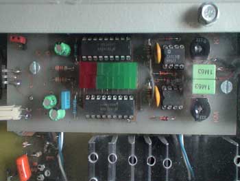
The circuit board.
Our Vu meter.