Electronics tutorials
Viewed products
-

Pic programmer
To program the microcontrollers we...


Pic programmer
To program the microcontrollers we need hardware and software that can program our microcontroller model. We’ll first explain the hardware model with the circuit PICs programmer which we described at this web page, and then we’ll learn how to use special software to program the microcontrollers which works perfectly with the programmer we propose you.
More info
Let’s start with the hardware:
Here we’ve made an electric scheme design and the printed circuit board with the design program “Eagle”, you can download and adapt them according to your taste.
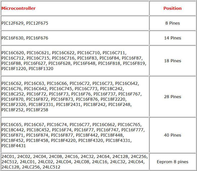
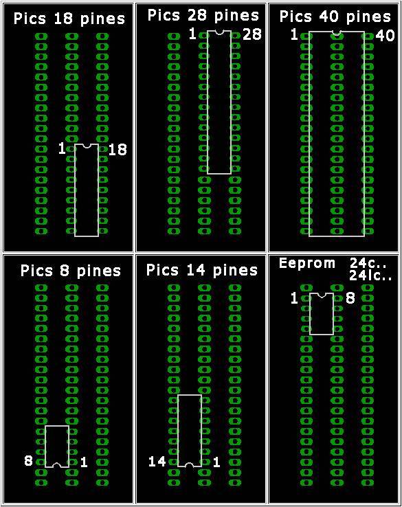
With this circuit you can program pics made of 8, 14,18,28 and 40 pins. You can also program Eeproms type 24C and 24LC..
In the second revision, the programmer’s features have been amplified, by expanding the microcontrollers’ models to program.
The relation quality-price is incredible, since we can program a great quantity of microcontrollers’ models with little money.
The programmer is connected to the Pc’s series port, later on we’ll see the exact model which we’ll select in the software to program the microcontrollers with our circuit.
In the following table we can see the microcontrollers’ models which we can program. In all PICs models, the programmer functions with the different versions of each model (-P, -A, -B, -JW), as well with the low consumption versions (16LF and 18LF).
These models, being redundant, aren’t included in the table.
The electric scheme is quite simple.
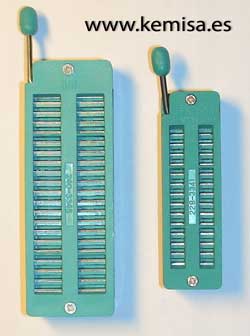
If you are going to use this programmer frequently, it’s going to be useful to place a ZIF socket (socket from outside of zero insertion) in the sockets destined to the PIC’s collocation, this way we can place the microcontroller without effort and the programmer connections and PIC’s pins won’t suffer at all.
ZIF socket, socket from outside of zero insertion.
The design of the printed circuit board. In the upper part there is a port connection RS-232, to connect it to PC.
The scheme and the circuit board should be in the same folder and they should have the same name, you should only change the extension to .sch for the scheme and to .brd for the circuit board, this way both of them will be recognized and associated by Eagle.
A photo of our Pic programmer.
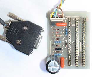
Pics programmer assembled with 40 pins ZIF
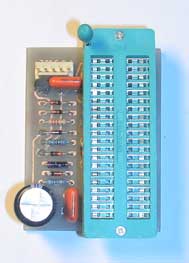
Pics programmer assembled with 28 pins ZIF

In the following table we can see different positions where we can place the PIC depending on the number of pins.
ANow we’ll start describing the necessary software for the microcontrollers’ programming.
After trying out various programmes of microcontrollers’ saving, the most convincing one was “WinPic800”. It’s free software, quite simple to manage, it supports many programmers, it’s translated to many languages and, what’s best of all, never fails.
We download it on this web page and we choose "download".
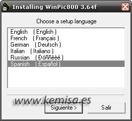
We double click on the .exe file, we choose the language and we click on “Next”.
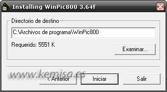
It tells us where the program will be installed, if want to change it we can do it, (we are going to leave just where it is), and then we click on “Start”.
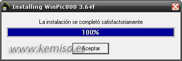
If the programme has been installed correctly, the following screen will appear, we’ll click on “OK”.
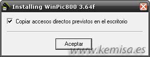
The next window asks us if we wish a direct access copied in the desktop, if we do wish to do it we click on “OK”, if not, we unmark the box first and then click on “OK”.
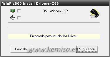
Then the program installs the drivers and we click on “Next”.
The installation is complete and then we see marked icons’ boxes of the upper left part
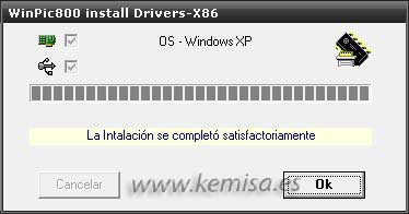
We click on “OK” and the installation finishes.
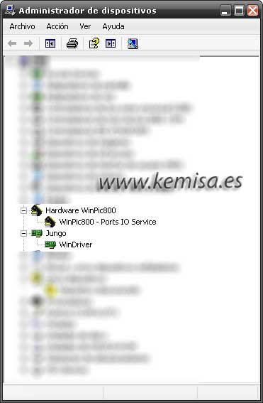
If we check the device administrator on our PC we’ll see that the two new ones have been installed, Hardware WinPic800 (Ports IO Service) and Jungo (WinDriver).
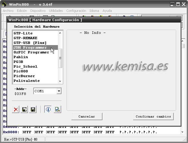
Now we open the programme and first we choose adequate hardware, we go to the “Configuration, hardware”.
We choose JDM Programmer, which is hardware we have to select so that we can program microcontrollers with our circuit; we click on “Apply changes”.
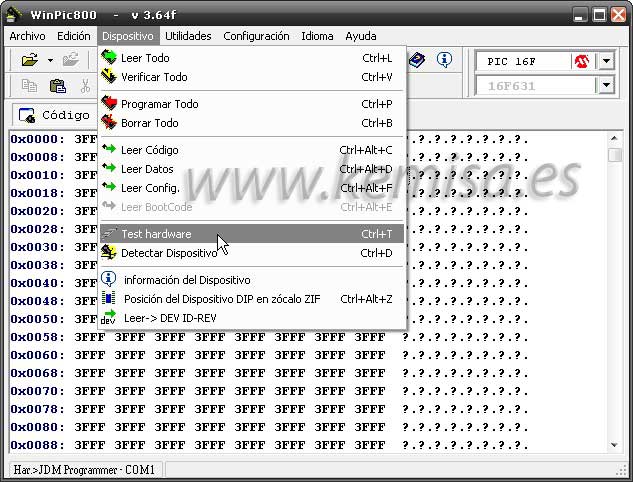
Let’s check if the communication of our circuit with software is correct, to do this we’ll go to “Device, Hardware test”.
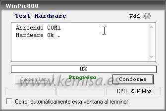
If everything is OK, we’ll see this: “Opening COM1, Hardware OK.” Click in “OK”.
Now we open a programme in .hex, for example, the calendar clock with the alarm and thermometer and we check if the microcontroller can be programmed.
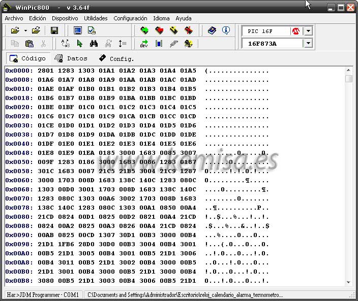
Before we open .hex we should select the Pic, we go to the Pic selection windows in the upper right part and in the first one we click 16F, in the second one, a 16F model (16F873A).
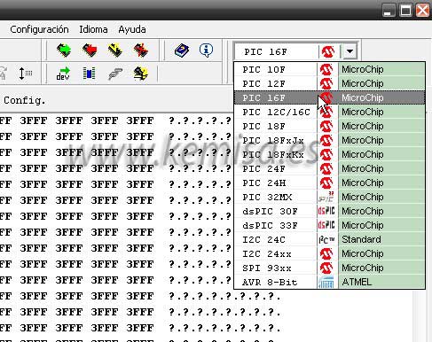
Now the model.
Now we load .hex programme, to do so we click on “Open Folder”.

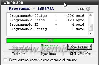
We choose the .hex code, in this case we choose “clock_calendar_alarm_thermometer.hex” and the code is opened in the programme’s main window. Once we place the Pic in its correspondent place in the programmer’s base, we click on “program all”
![]()
In the next window we’ll see a red line, an indicator of the programming process. If everything goes well, in the end of the programming, the red line will turn to green, which indicates that the programming was performed correctly. Click on “Accept”, we pull out the programmer’s pic and... Ready to work!