Home circuits
Viewed products
-

Light dimmer circuit
This simple circuit is made in order...


Light dimmer circuit
This simple circuit is made in order to regulate the luminous intensity of one or several incandescent lamps, or, as we know them, light bulbs, with a potentiometer.
Data sheet
| Design | Schema and circuit |
| View | No display |
| Supply voltage | 220 Volts |
| Electronic | Analog electronics |
| Photo | Yes |
More info
The maximum intensity which can withstand this design is around 500 watts.
There isn’t a lot to comment about the scheme: it is based on the TRIAC (triode for alternating current), which has a potency BT136, and it controls the luminous intensity depending on bigger or smaller resistance applied to “Gate” .
The 500K lineal potentiometer is in charge of this regulation. The R2 resistor serves to regulate the minimal light threshold.
We have included a 100 uH coil and a 100K condenser to free the circuit from the possible interferences which might be caused in the electric current while it is functioning.
The electrical connector for three connections is meant to connect:
-In the connection (X2-3) one electric current pole and one light bulb terminal.
-In the (X2-2) another light bulb terminal.
-And, in the (X2-1) another electric current pole.
The potentiometer had to be placed in the centre because of esthetical reasons.
Since the box wasn’t placed high enough, we had to make a hole in the panel to build in the potentiometer (see the photos below), so we included two “pinheads” (JP1 and JP2), to which we connected the switch’s terminals that were incorporated in the potentiometer.
The wiring diagram.
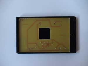
The circuit board.
We have placed the coil and TRIAC in the lower part of the panel since the height of the box was preventing us to put it in the vertical position.
By the way, the box is a “Supertronic, reference PP6N”.
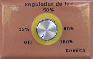
Our light dimmer.
The panel of the circuit bears a rectangular hole for the potentiometer in its centre.
Details of the connection switch potentiometer in the wiring scheme marked as "Pinhead" JP1 and JP2
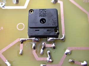
The components welded together on the panel.
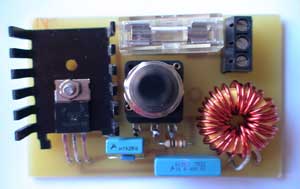
Finished light regulator.