Home circuits
Viewed products
-

Digital clock with display
This clock is for nostalgic people...
 View larger

Digital clock with display
This clock is for nostalgic people from “another electronic age” (without microprocessors). It’s a digital “old fashioned” clock and it’s already seen too many winters.
Data sheet
| Design | Schema |
| View | Display |
| Supply voltage | 12 Volts |
| Electronic | Digital |
| Photo | Yes |
More info
The clock is assembled throughout various stages that we shall now describe.
The first of them consists of the integrated circuit IC1, a 4060, which is a 14 stage binary counter in charge of dividing the frequency generated by the 32, 768Hz crystal and generate exit frequencies.
To be precise, at the tab 3, we place a 2 Hz signal, another 64 Hz at the tab 13, and the 2048 Hz signal at the tab 7.
This signal passes to the next integrated circuit, IC2, a data selector with eight entrances and one exit.
During the normal function of the clock, through the exit IC2 (tab 14), the 2Hz signal is selected by default.
In the adjustment phase, using the switches P1 and P3, we could select a 64 Hz frequency for a slow set up of the clock, and using the switches P1 and P2 we select a 2048 Hz frequency for the fast set up.
The 2Hz signal follows its way from IC2 to IC3, a CD4040 integrated circuit. This integrated circuit is in charge of dividing the 2Hz frequency between 120, that is, it generates an impulse each minute.
This impulse is taken by a IC4-A, a 4158, which is a double counter. The first counter is in charge of counting the minutes and the second one (IC4-B) counts tenth parts of the minute while the double counter IC5 counts the hours (IC5-A) and the tenth parts of the hours (IC5-B). The integrated circuits IC6-IC9 are in charge of turning on the LED-s of the displays to show the numbers.
The displays are made with common cathode.
The diodes D6 and D7 serve to divide between 60 (minutes from 0 to 59) and the diodes D8 and D9 between 24 (from 0 to 23 hours).
The set up, as we have already mentioned, is done by simultaneously pressing the switches P1 and P2 for the quick set up, and P1 and P3 for the slow set up.
Finally, we have added a small source of power of 12 volts and 300 mA, with a power regulator 7812, for the empowering of electric current.
The wiring diagram.
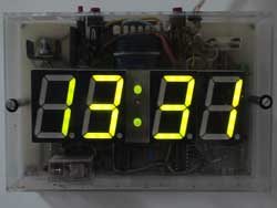
A photo of the clock assembled years ago, we lamentably painted the tracks by hands; that’s why there is no printed circuit.
This clock has a relay that activates at 00:00, changing the colour of the displays.