Pic circuits
Viewed products
-

In-out thermometer
In-out thermometer with 16F873A...
 View larger

In-out thermometer
In-out thermometer with 16F873A microcontroller.
Data sheet
| View | Lcd |
| Supply voltage | 5 Volts |
| Electronic | Digital |
| Photo | Yes |
More info
The electronic designed with the PIC microcontrollers allows us to create simple and practical circuits, like this indoors and outdoors thermometer that we suggest you should use.
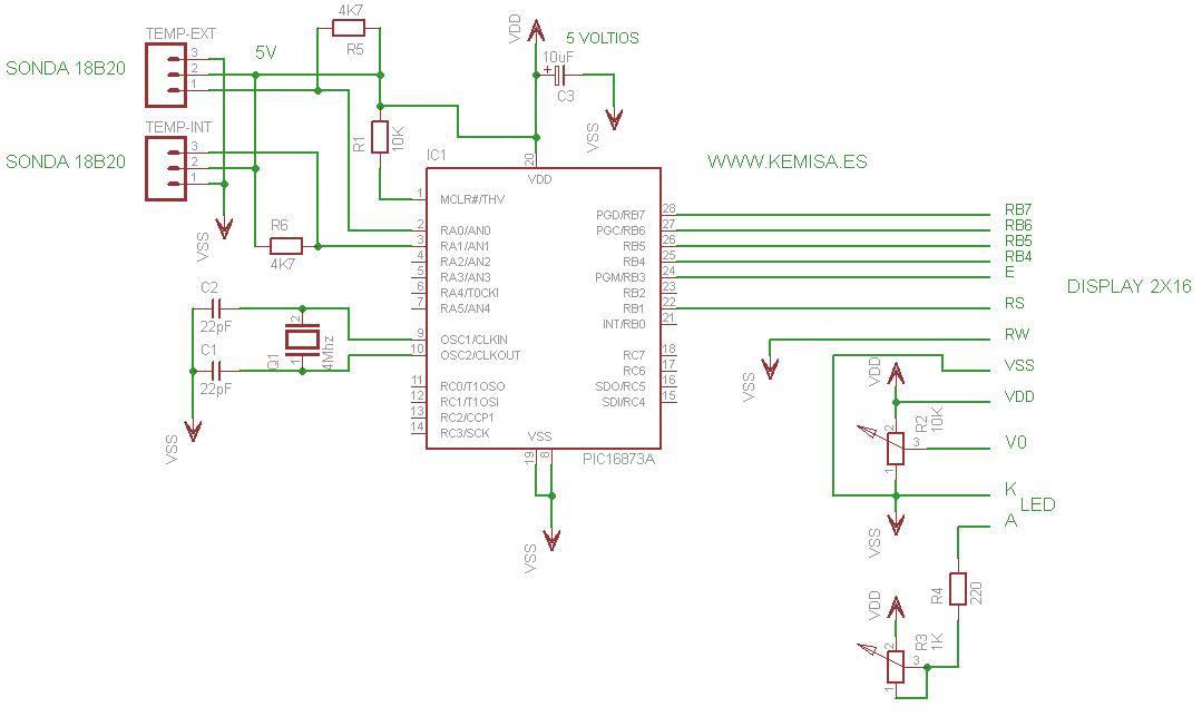
The circuit is based on a 16F873A controller. We have designed a program for this PIC, which is in charge of measuring of the indoors and the outdoors temperature.
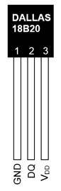
To measure the temperature, we have used the known probes, the one-wired ones, DS18B20, and a wire; they communicate with PIC using the digital data in only one channel.
These temperature sensors have a precision from 9 to 10 bits, and the measure range from -55ºC a 125ºC, with a margin of error of 0.5ºC. In our case, the measure goes from -55ºC to 99ºC.
Each sensor is fabricated with a 64 bit serial number which permits us to parallel connect multiple sensors but using only the microcontroller’s pin as a data bus.
In our case we haven’t placed it parallel (we had free PIC connection), but we placed each one to one 16F873A microcontroller’s pin; to RA0, the interior probe and to RA1, the exterior probe, to be precise.
The program we have designed communicates with the probes DS18B20 (DS18B20 probe’s datasheet), using the data bus pin by pin with each one, and updates the measures approximately every second. Don’t try to use a different probe model, since the circuit works correctly only with DS18B20.
The display we used is a LCD 2x16 with a Hitachi HD44780 controller or a compatible one (Hitachi HD44780 controller’s datasheet).
The electric scheme, it is obvious, goes around the microcontroller 16F873A (datasheet from the family of controllers 16F87XA)
The exits from the PIC RB1, RB3-7, are the communications with the LCD’s controller Hitachi HD44780 .
We have used a 4bit communication to show the data on the screen. The screens PIN RW is to be connected to the ground. Also, the LCD’s display contrast (V0) is done by the R2 10 K adjustable resistor, with its connected extremes, one at the positive pole and the other at the negative pole.
Our screen has a backlight, and that is why the LED or the LEDS that illuminate it are regulated by the variable R3 1K resistor.
The R4 resistor has a mission to protect the LEDS and to prevent that they assume more power than necessary, which could lead to their destruction.
The remaining components we wanted to comment on are the 4Mhz quartz, indispensable so that the program etched in PIC can start, the 10K resistor connected to the positive pole on PIN1, the PIC’s reset and the resistors R5 and R6 between the entrances of the temperature probes DS18B20 and the positive pole of the current.
Theoretically, the maximum distance at which we could connect the probes would be 6 or 7 metres, but we have managed to connect them on more than 15 metres of distance, with a simple trick: we placed another 4k7 resistor in the probe; that is to say, it was like putting two parallel resistors, one in the printed circuit and another one on the other extreme of the cable, between the pins of the signal exit and the DS18B20 probe’s positive pole.
The electric scheme with the PIC as the protagonist.
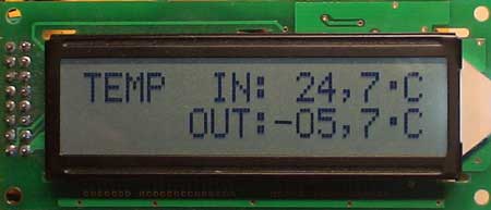
A photo of a working display.
In this case we haven’t created the board of the printed circuit since it greatly depends on the dimensions and connections of a LCD 2x16 display.
The .hex code is compressed within the free WinRAR program. You need WinRAR to extract it and the password is www.kemisa.es.
The .hex code is a program that you have to save in the PIC microcontroller 16F873A.
If you do not know how to program microcontrollers click here.