Audio circuits
Viewed products
-

Speaker protection circuit
This circuit is made to protect the...
 View larger

Speaker protection circuit
This circuit is made to protect the speakers from the "pump" inconvenience, that is produced in some amplifiers while they are on.
Data sheet
| Design | Schema and circuit |
| View | No display |
| Supply voltage | 12 Volts |
| Electronic | Analog electronics |
| Photo | No |
More info
The circuit, (based on the well-known and versatile NE555) is a timer with a delayed start.
When the circuit is empowered, the integrated circuit delays the activation of the relay connected to its pin 3.
The delay time can be adjusted with the P1 potentiometer. We can increase the delay even more if we increase the value of C1.
The positive output of the amplifiers loudspeakers is connected to the relay’s entrance and its output is connected to baffle.The power of this circuit is 12 volts.
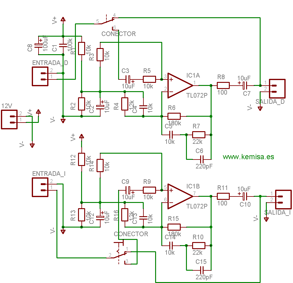
The wiring diagram.
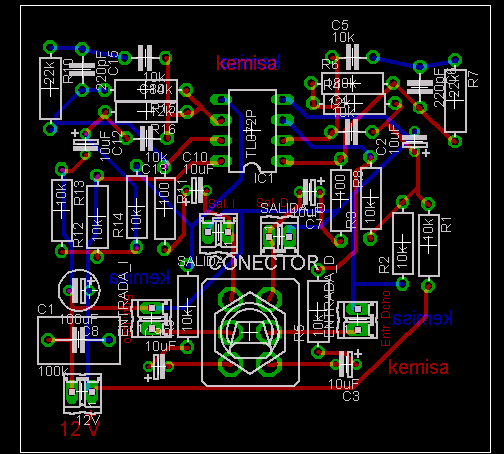
The circuit board.