Electronics tutorials
Viewed products
-

How to use the PC like an oscilloscope
With this simple tutorial we’ll...
 View larger
How to use the PC like an oscilloscope
With this simple tutorial we’ll construct an entrance to the computer to make it usable like an oscilloscope. We shall transform our PC into oscilloscope.
More info
With this simple tutorial we’ll construct an entrance to the computer to make it usable like an oscilloscope. We shall transform our PC into oscilloscope. An oscilloscope is maybe the most want measure instrument by all the people who like electronics.
It is most wanted since it is a very expensive instrument and not all electronic fans can afford it. However, we can transform our PC to a homemade oscilloscope with the acceptable benefits.
What we are going to do is used our PC’s sound card like an entrance, and a special software to show the signals we’ll apply at the entrance.
Before we continue, we have to make one thing clear: the signals can be measured with the alternate current signals, not the direct current ones.
The reason for this can be found in our PC’s sound card (in practically all of them). In this card there is an electrolytic condenser which blocks the direct signals that we might apply at the entrance as the protection measure.
The software we are going to use will show us our PC’s monitor with an aspect of an oscilloscope.
Let’s explain it step by step:
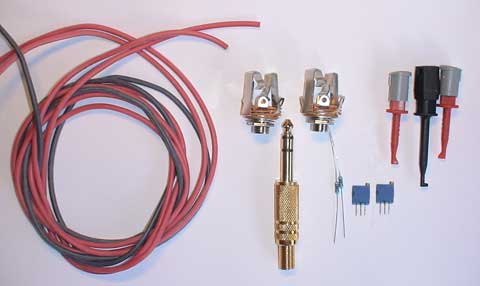
As far as the hardware is concerned, we will be needing:
2 metres of the flexible red wire
1 metre of the flexible black wire
rn- rn
2 6,3 mm female jack stereo connectors
1 6,3 mm male jack stereo connector
2 red test clamps
1 black test clamp
2 100K ohms resistors
2 20K trimmers
Components used
What we are going to make are two different entrances for the line entrance of our sound card. One entrance will go without attenuation, while we’ll make a resistive divisor x 0.1 on the other.
That is to say, at the second entrance, all the signals will be 10 times attenuated. (If you don’t know how to make a voltage divider, consult our tutorial on how to do it).
In general, sound cards admit 5 volts maximum, and that is why we can’t measure any alternate signal, since that would burn the sound card. With the resistive divisor x 0.1 we can measure 10 times more, which are 50 volts, since 50x0,1=50 volts.
We can make as many entrances as we wish; in this case it would be good to replace female jack connectors with a rotary commuter which will have as many positions as many resistive dividers we want.
The scheme would look like this.
We will do the resistors’ calculation by applying the formula. (For one channel)
Being VCC/2 the exit towards our PC’s sound card (OUT-L and OUT-R) and VCC the entrance we want to measure (JACKx0,1)
If we wish to make a resistive divider which will multiply by 0,1, the values would be:
For the channel L: R1=100K y R3=11K
For the channel R: R2=100K y R4=11K
Since we want the multiplication to be exact, we have to put a variable 20K resistor, and so, approximately towards the middle of the circuit (a little bit further), there will be the 11K we need.
We can make as many resistive dividers as we like. The adjustment of the trimmers, one for each channel, is quite simple.
We place an alternate power at the entrance without attenuation, and we apply the same power at the attenuated entrance, we turn the trimmer slowly until we obtain the 10 times less power.
It is highly advisable to adjust this before plugging in the line entrance to the sound card.
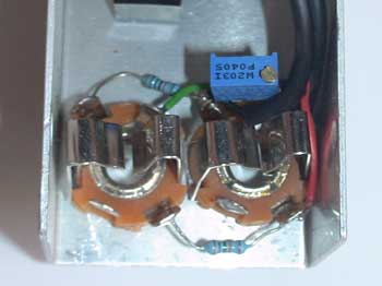
The box interior in the assembly phase, with the channel that leaves one entrance signal the same (x1) and the other entrance prepared to multiply x0,1. (Obviously, in a 0,1 channel there is no variable resistor).
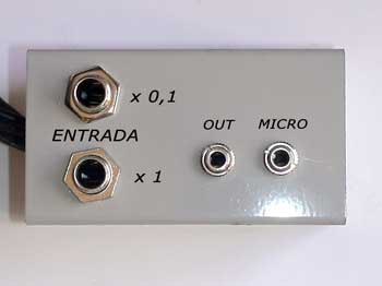
A completed box with the connections for the PC entrance by the line, with the multiplication x 0,1 and x1. Other connections of the line out and the microphone entrance.
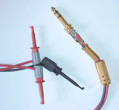
The probes are to be connected to a male Jack terminal. Each red cable is a channel, the black one, obviously, the ground.
A detail about connections of our probes for the oscilloscope.