Electronics tutorials
Viewed products
-

How to make a voltage divider
A resistive divider is an electric...
 View larger
How to make a voltage divider
A resistive divider is an electric circuit to which we join a voltage and so obtain its reduction.
More info
The resistive divider consists of two resistors, connected like in the following image scheme.
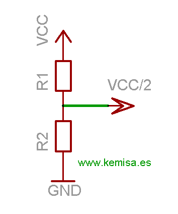
Joining a voltage to the point VCC, we obtain the voltage reduction at the point VCC/2. To calculate the voltage decrease at the point VCC/2, we apply this formula:

This way, we reduce the entrance power in function of the resistors’ values. Suppose we want to reduce the entrance power in half.
For example, we have a 12 volt power at the VCC entrance and we wish to reduce it to 6 volts at VCC/2. We shall put that R1=10k and R2=10k. According to the formula:

Por lo que VCC/2 = 6 volts.
According to the formula: VCC/2=6 volts.
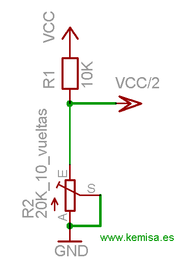
This is a theory, but in practice, the tolerance in resistors’ values makes that we really don’t have exactly 6 volts, but 6,1 or 5,9 volts. If we need an exact adjustment of the exit power (VCC/2), we should exchange the R2 resistor with a 20k trimmer and ten circles.
This way we vary the trimmer until we obtain exactly 6 volts at the exit VCC/2.