Pic circuits
Viewed products
-

Twilight switch
Twilight switch with 12F629...
 View larger
Twilight switch
Twilight switch with 12F629 microcontroller .
Data sheet
| Design | Schema |
| View | No display |
| Supply voltage | 5 Volts |
| Electronic | Digital |
| Photo | No |
More info
And... Many of you will think... Isn’t it easier to create a crepuscular switch with the classic NE555 than with a microcontroller?
Let’s analyse the circuits:
The number of components of a circuit with PIC and the other one with analogue electronics (NE555) are practically the same.
The price is slightly higher if we make it with the microcontroller, but the benefits are bigger.
Why is this circuit so special?
The extra we’ve added a normal crepuscular switch, it’s a delay when we turn on the light bulbs, or the machine connected to the relay out.
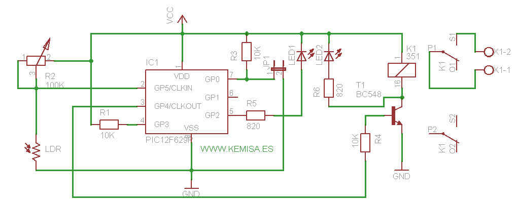
Let’s have a look at the electric scheme:
We have a photo resistor or LDR connected between pin 2 and the negative pole of the circuit power, and on the other hand there is a 100 K variable resistor between the positive pole and pin 2.
The LDR varies its resistance depending on the light which falls on it. And this photo resistor connected to pin 2 will vary the voltage on that pin depending on the light and the adjustable resistor R2.
In other words, varying R2 we can make the relay active when the light that falls on the photo resistor is minimal, at twilight, for example.
This electronic circuit is thought to turn on, for example, the house or garden lights at twilight and turn them off at dawn, but... Didn’t you realize that when the lights are turned on by LDR there is still enough exterior light to see?
We can adjust the threshold of the relay so that it turns on when practically nothing can be seen, and when the dawn is approaching, minimal light can make the relay turn off.
The solution lies in the delay of the relay activation.
That’s what is so special about this circuit.
Between the pin 7 and the ground there is a jumper. If the jumper is open, the relay will activate when we have programmed it to turn on by R2, but when it’s closed, connected to the ground, the relay will activate when approximately half an hour passes from the programmed by R2.
The led D1 diode will turn on when we have programmed it to do so by the variable resistor R2, and the led D2 will turn on when the relay is activated .If we remove the jumper the leds will turn on at the same time and the relay will activate.
If the jumper is there, D1 will turn on according to the program (the relay won’t activate) and D2 will turn on half an hour later, which is when the relay also will activate.
The microcontroller of this project is a 8 pin pic model 12F629. The power of the circuit is 5 volts in direct current and the consumption will be the consumption of the relay and the activated leds, with the power sours of the 5V, 100mA is quite enough.
The .hex code is compressed, to extract it, you should enter a password: www.kemisa.es
The .hex code is a program that you have to engrave in the microcontroller 12F629, which is necessary for the circuit to function.
If you do not know how to program microcontrollers click here.