Home circuits
Viewed products
-

Digital thermometer circuit
A very precise digital thermometer...


Digital thermometer circuit
A very precise digital thermometer with LM35 probe (0,1 degree of freedom).
Data sheet
| Design | Schema and circuit |
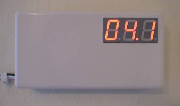
| View | Display |
| Supply voltage | 12 Volts |
| Electronic | Digital |
| Photo | Yes |
More info
The circuit has two adjustments. One of them, R5, adjusts the displays to 0.
To perform this, we have to connect the extreme part of R4 (that goes to the temperature probe) to the ground and we turn R5 until we see 0:0:0. Afterwards, we connect the probe LM35 to terminals 2 and 3 which are marked in the circuit. This is how we empower the probe.
Then we measure the values between the non connected terminal, which is the out of the probe, and the ground, with the tester, adjusted to 1 Volt (bottom of the scale). The tension which is shown represents the temperature in the room.
For example, if it marks 0.236, the temperature is 23,6 C. When we have the measure, we connect the terminal 1 of the probe to the circuit and we adjust R7 until it gives us the value of what we had measured.
The wiring diagram.
The circuit board.
A photo of the finished thermometer.