Pic circuits
Viewed products
-

Calendar clock
With the already known...
 View larger

Calendar clock
With the already known microcontroller PIC 16F873A and the integrated circuit DS1307 we have built this calendar clock.
Data sheet
| Design | Schema |
| View | Lcd |
| Supply voltage | 5 Volts |
| Electronic | Digital |
| Photo | Yes |
More info
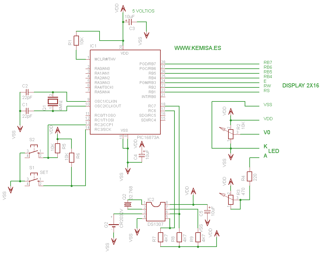
The circuit is quite simple; the program engraved in the PIC serves to read seconds, minutes, hours, day and month of the year with the “two threads” bidirectional bus I2C, the data of the integrated circuit DS1307.
The above mentioned circuit is a Real Time Clock, which starts counting the time from the moment we start it. In other words, we adjust the hour, minutes, seconds and the data, we communicate it to DS1307, we start it, and from there the microcontroller PIC 16F873A reads the data that the integrated circuit DS1307 sends it each second. Here you have a datasheet of DS1307.
The battery connected between the terminal 3 and the negative terminal is a battery model CR2032 which makes sure that the clock goes on ticking even though the power supply of the circuit stops.
This battery should be made of lithium and we’ll change it, just to make sure, each 5 years approximately to guaranty that the clock keeps functioning it there is a power cut. DS1307 is highly stable and precise. It’s precise because of the quartz connected to its terminals 1 and 2.
We have measured the differences and they are about 10 seconds a month, or two minutes a year, which is not bad at all. The integrated circuit DS1307 has in its memory the years of this century until a year 2100, including the leap years, of course.
The electric scheme is quite simple. It is composed of the microcontroller with its associated components, 4Mhz quartz with its 22 pF capacitors, a 10K resistor between the PIN 1 and the positive pole of the power, two switches connected to the two entrances RC2 and RC3, and the 4 bits data bus to manage the display.
The 16F873A connection with the DS1307 integrated circuit is made by an I2c bus with the RC6 and RC7 ports from microcontrollers to the pins 5 and 6 of the integrated circuit DS1307.
It will be visualised on a LCD display 2x16 (as long as it is a display with the Hitachi controller HD44780 or compatible one, with the datasheet of a Hitachi controller HD44780).
The LCD display contrast (V0) is made by the 10K adjustable resistor R2 with its extreme ends connected respectively to a positive and negative pole. Our screen has a back light, so the LED or LED-s which illuminate it is regulated by a variable resistance R3 (470 ohms).
The resistance R4 protects the LED-s and prevent that they consume more energy than necessary, which could lead to their imminent destruction.
The switches S1 and S2 are used to adjust the clock. The adjustment is a simple one. First time when we turn on the circuit we will see the hour 00:00:00 and the data 1/1/2011.
We press the switch S1 during one second approximately, marked as SET in the scheme, when we remove our finger we shall see the word SET on the screen and the cursor below the hours to adjust it.
We press S2 and we can advance the hours. Then we press S1 again and the cursor will be placed in minutes, we adjust it with the cursor S2 and we repeat the movements until we adjust everything.
After adjusting the year in the end, we press S1 again and send the data of our adjustment to DS1307, we shall see “OK” on a display, and from then on the clock will begin to count.
The circuit is empowered with 5 volts of direct current and its consumption won’t be over 100mA with the LCD display light turned on; therefore, the power source, which will remain on for 24 hours a day, 365 days a year should provide us with 5V and 200 mA.
rn
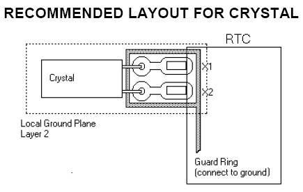
According to the datasheet DS1307 the body of quartz crystal is to be connected to the ground and its terminal as close as possible to the pins 1 and 2 of DS1307, as you can see in the photo.
The electrical scheme. It's very simple.
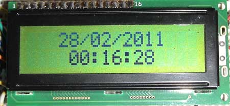
A photo of the prototype calendar clock
We have developed a version with the alarm and the thermometer which you can see on the page: “calendar clock with the alarm and thermometer".
The file is compressed, to extract it, you should enter a password: www.kemisa.es
The .hex code is a program that you have to engrave in the microcontroller 16F873A, which is necessary for the circuit to function.
If you do not know how to program microcontrollers click here.