Power supply circuits
Viewed products
-

Power supply arrangements
That power supply may be configured,...
 View larger

Power supply arrangements
That power supply may be configured, because depending on our voltage regulator, we’ll get more and less current at its output.
Data sheet
| Design | Schema and circuit |
| View | No display |
| Output Voltage | Configurable |
| Output Current | Configurable |
| Electronic | Analog electronics |
| Photo | No |
More info
That power supply may be configured, because depending on our voltage regulator, we’ll get more and less current at its output. See below the graphic in order to assemble the most suitable power supply needed.
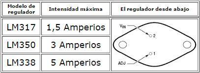
There is no much comment to make about the power supply. It is made up of a rectifier REC1; a filtering through the condensers C1 and C2; a current regulator that, in view of our needs, we will choose from the graphic above, C4 and C5, in order to avoid fluctuations in the output. The output voltage control is carried out through R1.
The connector (CON2) is ready for connecting a LED to show that the power is on. In addition, the SMD LED marked LED1 will light up if the fuse has blown, provided that we have electricity running in the terminals of the power supply.
The trouble with voltage regulators belonging to the LM family ... is that if the voltage difference between the input (3-pin of CON1) and the output (1-pin of the CON1) is too big, the heat they would generate will also be high, is also great; in fact the heat is proportionate to the voltage difference multiplied by the consumption at that moment.
Power (in watts) is equal to Volts multiplied by Amps. P = VxI
In that case, V is the difference between the controller input and the controller output, and the AMPS is the consumption in the circuit output.
If we set out to make a power supply, and given that we don’t need to have such a wide margin of tension, we’ll make sure there isn’t a lot of difference between the voltage of the transformer input and the tension wanted at its output, seeing that the regulator will have to dissipate more heat as the difference increases.
If we set out to use the current power supply with more than two AMPS, and with a difference of more than ten volts at the voltage regulator for a long time, it is advisable to remove the regulator from the power supply box and make sure that there is a bigger heat sink for proper ventilation.
The wiring diagram.
The circuit board.