Power supply circuits
Viewed products
-

10 amp variable power supply
With the familiar LM338K voltage...


10 amp variable power supply
With the familiar LM338K voltage regulator and a high-powered transistor, the 2N6031, we have set up a powerful 10-amp variable power supply.
Data sheet
| Design | Schema and circuit |
| View | Lcd |
| Output Voltage | Regulable |
| Output Current | Up to 10 Amp |
| Electronic | Analog and digital electronics |
| Photo | Yes |
More info
The highest output power depends on the voltage difference between our transistor and voltage regulator input and the output we wish to get. The regulator will have to dissipate more heat as the voltage difference increases.
Here you can see the LM338K data sheet, and refer to the linked 2N6031. From the data sheet of the 2N6031 transistor you´ll find out that the maximum electric current hits a highly significant 16 amps and even peaks at 20 amps.
The maximum temperature that brings destruction is 200 degrees and the thermal resistance JC, reaches its limit at 0.875 °C / W. These data show that we are talking about a 16-amp variable power supply at its best.
It is standard practice to always oversize the power antes de su destrucción es de 200 grados y la resistencia térmica JC, es decir la unión al encapsulado es de 0,875 ºC/W.
The power suppy never go over 70% of the maximum power in accordance with the manufacturer´s instructions. In this case, 70% of 16 Amps = 11.2 Amps.
There is little to say about the electrical circuit.
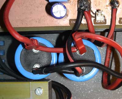
The electrolytic capacitors and the rectifier are not included in the schema and will be set separately.
Two 4,700 uF capacitors in parallel have been chosen for the electrolytic capacitors, making a total of 9,400 uF.
We have fitted them next to the printed circuit in an upright position.
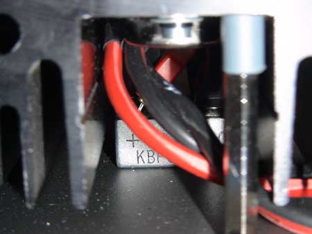
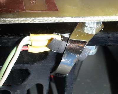
As for the rectifier, it is possible to fit it either to the cooling fan or on the bottom of the metallic box.
We have opted to fit it on the bottom of the metallic box, below the cooling fin where we have positioned the integrated LM338K and the 2N6031 transistor. In order to prevent whirring, it is necessary to connect the negative pole of the rectifier with the frame of the metallic box.
The integrated voltage regulator and the transistor are not described as such in the schema except for their connections. Their holes therefore appear in the circuit board in order to place them under the printed circuit board.
The resistance sensor (located at the center of the cooling fan) is a separate issue. You don’t need to connect that resistance if you don’t intend to use our voltmeter-ammeter-wattmeter with pic. The function of that resistance is to establish a potential difference between its tips, according to the electrical current delivered by the power supply.
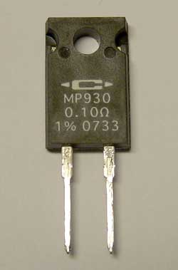
It is absolutely necessary to fix the resistance parts to a cooling fin. Otherwise, the high temperature will destroy it. This is a 0,10 ohms and 30-watt resistance, which works to a tolerance of 1%. A real gem! See here its design features.
Suppose that the power supply is delivering 1 amp. In accordance with the formula:
Potential Difference (V) = Intensity (I) X Resistance (R).
Between both extremes of the resistance there will be a voltage such as V = 1x0.1 and V = 0.1 volts. That 0.1 volt reads 1 Amp according to our pic.
This is its drawbacks: the volts originated in the power supply must be measured before going through the resistance, hence the error in calculating volts amounts to 0.1 volt per ampere. If we measure 10 amps instead of 1 amp: V = 10x0.1 and V = 1 volt. This is the maximum error in calculating the real amount of volts provided by the 1 volt power supply when we are getting 10 amps..
Have a look at the diagram of the wiring system.
The bottom part of the wiring diagram catches mostly our attention. We have designed a “preset” system or a three voltages selection by using a switch. To this end, we have specially adapted our three-relay sequential circuit on-off switch.
We have replaced from it the output transistors to the relays for a molex connector of four contacts, the first three for every relay and the fourth for the positive pole of the power supply.
Connected to the relays there are 2 variable resistors (R5 and R9) and a connector that will be linked to the potentiometer knob located on the front of the case to vary the voltage.
With the help of the variable resistors R5 and R9 we’ll regulate at will the tension we want to get when triggering the switch. We have a ready-made "preset" with 12 and 5 volts, which are our very usual tensions.
Thus, when giving a first press (without having to vary the potentiometer located on the front of the box) we get 12 volts and
5 volts with a second press. We vary the voltage thanks to the potentiometer.If you're not going to use the "preset" and you just want to vary the voltage by means of the potentiometer, connect it between C3, R4, D1 and to ground.
The printed circuit board design.
We have designed a ground plane to cover it and the negative pole with copper as much as possible. It is advisable to do so in order to prevent whirring in power supplies.
If you don’t know how to do it, see our tutorial to create a ground plane through Eagle. Apparently there are only two lines around the circuit, red in the "top"-side and blue in the "bottom"-face. To run ground plane on both sides, just click on the icon  .
.
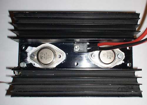
The achieved circuit.
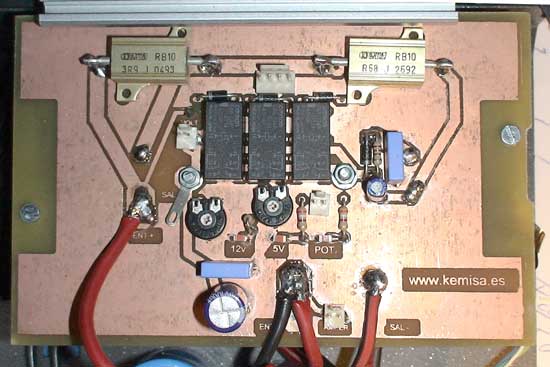
The described power supply is integrated and adapted to the voltmeter-ammeter-wattmeter with pic.
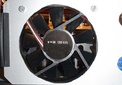
This circuit allows us to control the temperature of the power supply and set off a ventilator when the probe exceeds the programmed degrees.
To measure the temperature level we can put the probe (LM35) inside the box and gauge the room temperature, or it would be even better to connect the probe (with silicone paste in between) with the cooling fin. Thus, it will reveal the heat generated by the integrated LM338K, the 2N6031 power transistor and the current sensing resistance.
Moreover, given that we have put the rectifier under the cooling fan, it will be ventilated as well. And naturally the air flowing from the inside to the outside will cool the other components.
The back side of the power supply with the ventilator located behind the cooling fan.
The setting up is not complete without an on-off "elegant" switch. Have you seen better than our integrated circuit with an on-off push-button. The circuit design and the design of the “preset” control (three-relay sequential circuit on-off switch) are integrated with the voltmeter-ammeter-wattmeter board with pic.
And finally, two fuses haven been placed to protect the components against possible short circuits or surges. A 10 amp fuse for the output current and a 0,8 amp fuse for the alternating current (AC) input to the power supply.
Some pictures of the completed assembly.
Back side of the variable 10 amp power supply already completed.

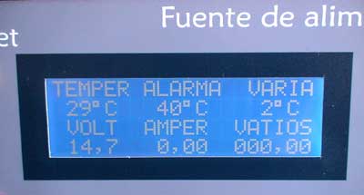
The frontal side of the power supply already completed with the voltmeter-ammeter-wattmeter display in operation.
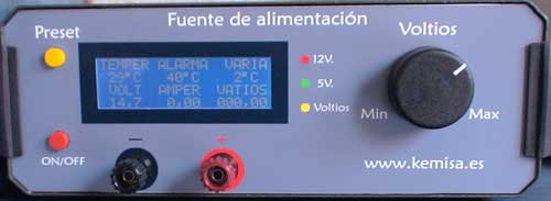
Voltmeter-ammeter-wattmeter display.