Pc circuits
Viewed products
-

Proximity sensor power on for Pc
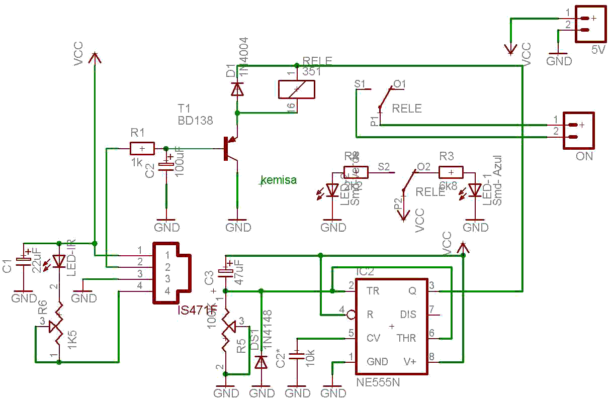
This circuit is based on the infrared...


Proximity sensor power on for Pc
This circuit is based on the infrared receiver IS471F. The running principle of the circuit is easy.
The transmitter is an infrared LED that emits a modulated signal monitored by the 4-pin of the IS471F.
Data sheet
| Design | Schema and circuit |
| View | No display |
| Supply voltage | 5 Volts |
| Electronic | Digital |
| Photo | Yes |
More info
Being reflected in a nearby object, the signal is bounced off and captured by the IS471F internal demodulator. The output originated in the 2-pin from the integrated circuit excites a relay that is connected to the computer on/off switch. The sensitivity can be adjusted through the R6 trimmer of 1K5.
The other integrated circuit, known as NE555, is a small delay so that when such a power there, when they return, the turning on your computer.
The NE555 retains those seconds the "peak." That period of time can be adjusted through the R5 potentiometer.
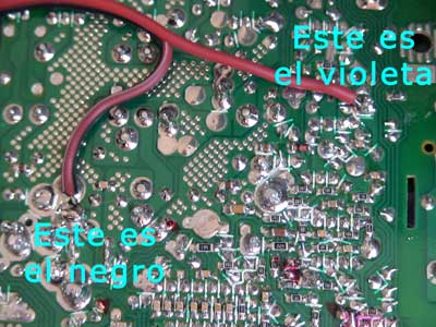
Finally, the 5 volts powered circuit can be obtained from the computer power supply. We´ll have to remove two cables from the 9-pin plugs (keeping the tension plate positive +5 V, and is usually violet), and any of ... 3,5,7,13,15,16,17 (the negative), these pins correspond to the black wires.
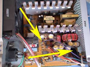
First of all, with the computer off, we recommend to gauge with a multimeter where in the ATX connection pins of our power supply, remains the tension of 5 volts which supplies the basic plate when the computer is off. From there we will get our 5 volts to power the circuit.
We will first turn on the power supply and find from where do the wires come out, violet and black.
Violet wire specifications.
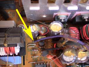
Now we watch carefully at the location in order to solder the wires on the side of the tracks. The picture of our power supply shows where the wires on the side of the tracks come out
That circuit works as a switch. If you want a switch sensor that can also be used as a switch to turn on any device, here you get an on/off sensor.
Now we have to replace the cable connected to the switch computer with our circuit output marked ON.
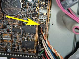
We have to replace the pins that go to the button on the front of the computer by the output of our circuit so that it is the one that turns on the computer.
The arrow indicates on the motherboard where is the power on button.
The wiring diagram.
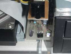
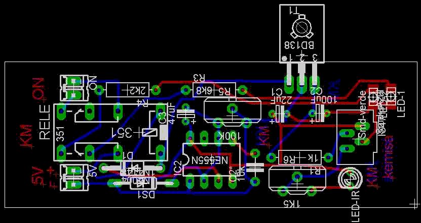
The circuit board.
The switch circuit operating in one of the computers.