Pic circuits
Viewed products
-

Digital voltmeter with LCD
With a simple circuit and a...
 View larger

Digital voltmeter with LCD
With a simple circuit and a microcontroller pic, 16F873A model, we designed this digital voltmeter in addition to any power source.
Data sheet
| Design | Schema |
| View | Lcd |
| Supply voltage | 5 Volts |
| Electronic | Digital |
| Photo | Yes |
More info
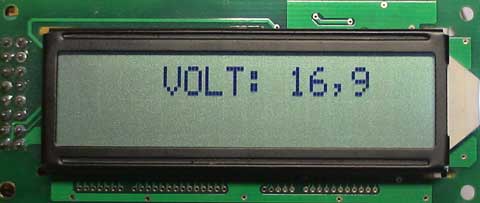
The measured voltage goes from 0 to 99.9 volts DC. The display is a 2x16 LCD screen. Any 2x16 LCD screen that carries the Hitachi HD44780 controller or compatible (datasheet Hitachi HD44780 controller) may be used to display the measurement in volts.
The circuit is based on the popular Microchip PIC 16F873A Microchip's house (family datasheet 16F87xA ). We turn to comment on the wiring diagram, which as you can see is quite simple.
The first thing we know is that our pic only supports voltages from 5 volts up on your posts, then how can we measure higher voltages?, Very simple, with a resistive divider.
We've built a resistive divider at the input pin to the pic (if you can not make a resistive divider click here), in this case the input is connected to pin 2 (RA0) through a resistive divider formed by the components R8, C3 and the R9 trimmer.
This resistive divider multiplies the input by 0.01 volts. That is, if we apply a voltage input connector CON1 of 12 volts, the resistive divider output, particularly in the leg would have a voltage RA0 12x0, 01 = 0.12 volts. This multiplication by 0.01 is achieved by adjusting the trimmer R9, set to be discussed later.
We used a 4-bit communication, to display data on the screen. The RW pin of the screen has to be grounded. Also, the contrast of LCD display (V0) is made by the adjustable resistance R2 10K, with its ends connected to one positive and one negative pole.
Our screen is backlight, and backlight, so the LED, or light LEDs that are regulated by the variable resistor 1K, R3. The resistance R4 mission is to protect the LEDs to prevent assume more power than necessary, which could lead to its destruction.
Now let's see how we adjust our pic to measure on a scale from 0 to 1023 (102.3 hata means volts) is saying and ignoring the first digit from 0 to 99.9 volts, and we have removed the first digit and have put a comma before the last, the measure is current.
So we must act on the reference voltage of the pic, the pin 5 is marked as RA3. For this we give power to the circuit (5 volts) we place a point TP1 tester body and the circuit ground and slowly turn the adjustable trimmer marked as R6 500 ohm reading on the tester to 1.023 volts, which is the maximum extent can be applied to input RA0 paw.
Now adjust the resistive divider so, we have exactly 100 times less in the output of said resistive resistor with respect to the input.
For this we give power to the circuit, we put a voltage input connector CON1 and then turning the trimmer slowly R9 to read LCD display on the stress that we applied to the input.
As we know, when we have an input voltage of 99.9 volts the CON1, we resistive divider output voltage of 0.999 volts, far from the 5 volts that allows a maximum of pic.
But beyond the 1.023 voltage stress Colti mark displayed on display 02.3 which means, if we put the first digit, 1023 which is the maximum that can measure the pic as the adjustment to the reference leg 5 (RA3) .
The circuit as we have said is supplied with 5 volts DC and the power consumption of only 20 milliamps.
A photo of the prototype digital voltmeter with pic 16F873A just described in this article.
The file to download is compressed, to extract it, you should enter a password: www.kemisa.es
The .hex code is a program that you have to engrave in the microcontroller 16F873A, which is necessary for the circuit to function.
If you do not know how to program microcontrollers click here.