Power supply circuits
Viewed products
-

A Digital voltmeter
This circuit is composed of two...


A Digital voltmeter
This circuit is composed of two integrated circuits. A digital analogue converter (CA3162) and a seven segment decoder (CA3161).
Data sheet
| Design | Schema and circuit |
| View | Display |
| Supply voltage | 5 Volts |
| Electronic | Digital |
| Photo | Yes |
More info
The circuit is empowered with 5 volts and it merely has two adjustments R2 of 47 K serves to put the displays on 0. To do this, we have to short-circuit the voltmeter entrance and turn slowly the R2 until we can see 0-0-0 on displays.
The variable resistor R1 serves to calibrate the power level.
To regulate this, we will insert 12 exact volts at the entrance, measured with of tester or proceeding from 7812 and we continue turning R1 until we can see 12 volts.
The circuit should be empowered with a small power source, 5V, and this way the maximum measure that our voltmeter can do is 99,9 volts.
If apart your digital voltmeter you need that your power source also measures the consumed amperes, check out our assembly of a digital ammeter.
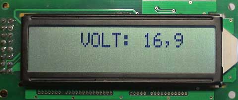
And if you need a voltmeter with a visualization on a LCD screen, consult a digital voltmeter page with a PIC 16F873A.
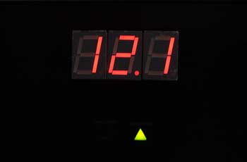
The wiring diagram.

A photo of our voltmeter in one of our power supplies.
And here is a photo of the display in the assembly of another digital voltmeter with a PIC 16F873A.